

 English
 Instrumentation Cable
Home / Products / Instrumentation Cable / 4 Pair 1.0mm² Multi-Pair Shielded Instrumentation Cable for Industrial Process Control

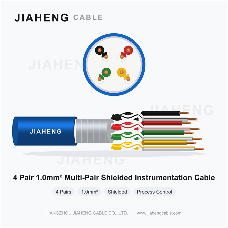
Confirmed by designation
• Pairs: 4 pairs (8 cores)
• Conductor size: 1.0 mm²
• Application class: instrumentation / process control signal
• Rated voltage: 300/500 V (typical)
1. Product Overview
This 4 pair 1.0 mm² instrumentation cable carries four twisted pairs — eight cores — inside one shared construction, providing a single cable run capable of serving four independent signal circuits between field instruments and a control system.
It occupies the middle of the instrumentation range. A single pair serves one measurement point; large multi-pair cables serve a marshalling cabinet with dozens of loops. Four pairs is the practical size for a package unit, a process skid, a pumping station, an analyser shelter or a machine control panel — situations where a defined, modest number of signals travel together along one route.
2. Why Multi-Pair Construction Pays for Itself
Installation cost on an industrial site is dominated by labour and containment, not by copper. Every additional cable run means another pull through duct or tray, another gland plate entry, another set of terminations, another entry in the cable schedule and more space in the containment.
Consolidating four circuits into one cable captures most of that saving. The four pairs share one route, one set of supports, one gland entry and one termination point at each end. For a skid-mounted package unit where the cable must pass through a single penetration in the enclosure wall, a multi-pair construction may be the only practical option.
3. Crosstalk Between Pairs: The Real Design Issue
When several pairs share one sheath, the dominant interference mechanism stops being external electromagnetic fields and becomes crosstalk between neighbouring pairs inside the cable itself.
The standard defence is differential twist lay. Each pair is twisted at a different rate, so energy coupled from one pair into another does not accumulate coherently along the length — the coupling reverses phase periodically and largely cancels. This is a manufacturing-controlled parameter, not an accident of construction, and it is what allows multiple analogue signals to coexist in one cable without measurable error at normal plant distances.
Whether individual pair screening is also needed depends on what the pairs carry:
• Four 4-20 mA loops in a standard plant environment: overall screening is normally sufficient.
• Mixed signal types — a millivolt thermocouple or RTD signal sharing the sheath with a higher-level signal: individual pair screening is worth specifying.
• Long runs adjacent to power cabling, or a plant area with severe interference: individual pair screening, or an overall foil-plus-braid construction.
Confirm which shielding architecture is actually supplied. "Multi-pair shielded" is an ambiguous description and the two options perform very differently.
4. Conductor Size and Loop Resistance
At 1.0 mm², the conductor is large enough that loop resistance is rarely the limiting factor for 4-20 mA circuits at normal plant distances. This matters because loop resistance adds directly to the transmitter's required drive voltage; if total loop resistance exceeds the transmitter's compliance capability, the signal clips at the top of the range — a fault that looks like an instrument problem but is actually a cable sizing problem.
The same cross-section also gives mechanical robustness for terminations that will be disturbed repeatedly during commissioning, and for direct installation in duct, tray or conduit.
5. Colour Coding: The Most Common Cause of Commissioning Delays
Eight cores in one sheath, four of which must be paired correctly, is a genuine opportunity for error. If pair identification is ambiguous, technicians will guess, and signals will arrive at the wrong input cards — a fault that can take hours to trace because every individual wire is electrically sound.
Before ordering, confirm the colour code and record it on the loop sheets and cable schedule. Where the project uses numbered or banded cores rather than solid colours, state this explicitly. Where individual pair screening is supplied, confirm whether each pair has its own drain wire, since this determines whether pair screens can be terminated without soldering to foil.
6. Applications
• Package units and skid-mounted process equipment with several field instruments
• Pumping stations and compressor sets: status, control and feedback signals together
• Analyser shelters and sampling systems
• Small DCS or PLC marshalling where a limited number of loops share one route
• Machine and equipment control panels in industrial installations
• HVAC plant rooms and building automation controller wiring
• Retrofit projects consolidating several existing single-pair runs
7. Earthing and Termination Practice
Screens only work when bonded. Standard practice for instrumentation circuits is to bond the screen at one end — normally the control room or cabinet end — to prevent circulating currents where the two ends sit at different earth potentials. Where individual pair screens are supplied, decide and document whether they are bonded per pair or collectively, and apply that decision consistently across the whole project.
Use wide-area bonding methods — shield clamps or EMC glands — rather than a thin twisted tail, and confirm that the marshalling cabinet provides a proper clean earth reference.
8. Ordering Guidance
Confirm the shielding architecture first, since it determines both performance and price. Then confirm conductor material, insulation material, pair colour code, presence of per-pair drain wires, overall diameter for containment planning, armouring if the installation requires mechanical protection, and jacket material where the location mandates LSZH. State the number and type of signals the cable will carry so the supplier can advise on the appropriate construction.
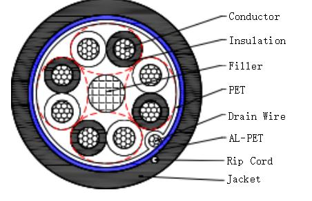
Technical parameter
| Type | 4P×1.0mm² Instrumentation Cable |
| (mm) Specification | |
| Conductor | |
| Conductor material | BC |
| ConductorConstruction(mm) | 7×0.4±0.01 |
| Insulation | |
| Insulation material | V-90 PVC |
| Insulation diameter (mm) | 2.0±0.1 |
| Average Thickness (mm) | 0.4 |
| Min Thickness (mm) | 0.35 |
| Color |
Black1-White1, |
| Fill | |
| Filler material | Fill the rope |
| Wrapping tape | |
| Wrapping tape material | PET |
| Drain wire | |
| Drain wire material | TC |
| Drain wire size | 7×0.2±0.01mm |
| Shield | |
| Shield material | AL/PET |
| Rip-cord | |
| Rip-cord | Yes |
Detailed technical parameters
| Type | 4P×1.0mm² Instrumentation Cable |
| (mm)Specification | |
| Jacket | |
| Jacket material | 5V-90 PVC |
| Jacket Diameter(mm) | 10.3±0.3 |
| Average Thickness(mm) | 0.95 |
| Min Thickness(mm) | 0.85 |
| Color | Black |
| Electrical&Physical Characteristic: | |
| Conductor DCR 20℃ | ≤21.4 Ω/km |
| Operational Temperature Range | -20℃~90℃ |
| Insulation Resistance(MΩ/km) | 320 |
| Inductance(@1kHz) | 0.95Mh/km |
| Max. Capacitance Conductor to Conductor(pF/m) | 300 |
| Max. Capacitance Conductor to Conductor(pF/m) | 200 |
| Operating Voltage-UL | 300V RMS |


 sales@jiahengcable.com
 +86-19357267601

 Heziwu, Shuangyuan Village, Linglong Subdistrict, Lin'an District, Hangzhou City, Zhejiang Province, P.R.China
Copyright © Hangzhou Linan Jiaheng Cable Co., Ltd. All Rights Reserved
