

 English
 Ethernet Cable
Home / Products / Ethernet Cable / CAT6A S/FTP LSZH Cable 23AWG 4 Pair Double Shielded for Data Centre 10G Cabling

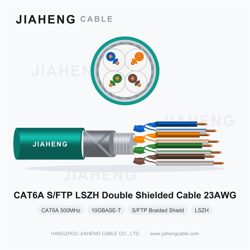
Confirmed Cable Specifications
• Category: CAT6A (Class EA), bandwidth 500 MHz
• Ethernet application: 10GBASE-T 10-Gigabit Ethernet, 100 m channel
• Shielding: S/FTP (also denoted as SF/UTP or SFUTP) — Individual pair aluminum foil shielding + overall copper wire braid, dual shielding
• Jacket: LSZH (Low Smoke Zero Halogen)
• Conductor size: 23AWG (approx. 0.57 mm diameter)
• Pairs: 4 pairs (8 cores)
1. Product Overview
CAT6A S/FTP LSZH 23AWG×4P is the highest-specification construction in this range: a 500 MHz, 10GBASE-T-capable four-pair cable in which each pair is individually wrapped in aluminium foil and the assembled core is then covered by an overall copper braid, all inside an LSZH jacket.
Two screens, doing two different jobs. Understanding that distinction is the whole point of this product — and the reason it should not be specified casually.
2. Two Screens, Two Jobs
The individual pair foils address internal crosstalk — interference between pairs inside the same cable. At 500 MHz, where 10GBASE-T operates, pair-to-pair coupling within one jacket is a significant impairment, and separating each pair in its own conductive envelope suppresses it at the source.
The overall braid addresses external interference and alien crosstalk. A copper braid is far more effective than foil alone at low frequencies and against magnetic-field coupling, because it provides a low-impedance, high-conductivity path that can actually carry intercepted current away. It is also mechanically robust, which matters during installation in dense containment.
Together they cover both threat directions completely. This is why S/FTP is the standard answer for the most demanding environments.
3. Where This Construction Is Justified
Specify CAT6A S/FTP where the penalty for network failure is high and the electromagnetic environment is severe:
• Data centres and server halls: thousands of cables in tight bundles, high-density patch fields, 10GBASE-T and above, and alien crosstalk risk at its maximum. The braid is what keeps adjacent links from interfering with each other.
• Industrial networks: manufacturing plants, process industries, power generation, rail and traction environments where variable speed drives, switchgear, welding equipment and traction power generate intense broadband interference.
• Facilities with strict EMC requirements: laboratories, medical imaging suites, test facilities, broadcast and media production, financial trading floors.
• Installations where the cable must share containment with power conductors and separation distances cannot be achieved.
• Critical infrastructure where re-cabling later is prohibitively expensive or operationally impossible.
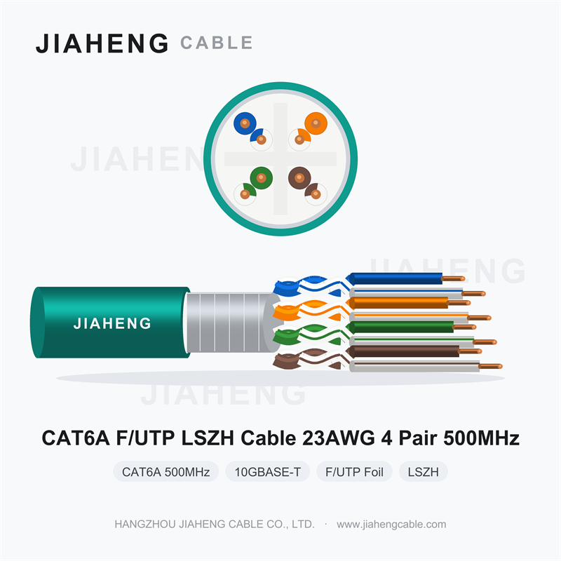
In a standard office environment, this construction is over-specified. F/UTP CAT6A — or in many cases CAT6 — delivers the required performance at lower cost, with less stiffness, smaller diameter and simpler termination. Specifying S/FTP everywhere "to be safe" adds cost, installation difficulty and, ironically, new failure modes through the earthing work that a proper S/FTP installation demands.
4. Braiding and Coverage
Braid quality is not a binary. Coverage — the percentage of the underlying surface actually occupied by copper — determines screening effectiveness, particularly at higher frequencies, and also determines mechanical robustness and current-carrying capability for fault and signal currents.
Coverage is a specification worth stating explicitly on the data sheet rather than leaving to assumption. A dense braid performs meaningfully better than a sparse one, and the difference is invisible once the jacket is on. Ask for the figure and, where the project warrants it, the transfer impedance measurement, which quantifies how well the screen keeps interference out across frequency.
5. The Earthing Obligation Is Real
S/FTP is the most demanding cable in this range to install correctly. Both screens must be handled:
• The overall braid is bonded to earth through shielded connectors, glands or clamps with wide-area contact.
• Individual pair foils must be managed at termination — folded back, trimmed or contacted according to the connector system used. Field technicians need the correct shielded CAT6A connectors and the training to use them.
• The earthing scheme must be deliberate. Single-ended bonding avoids ground loops; double-ended bonding with an equipotential bonding conductor is used where high-frequency performance requires it and where the building's earthing supports it.
Budget for the hardware and the labour. A data centre full of S/FTP cable terminated into unshielded connectors is an expensive mistake that delivers F/UTP-level performance at S/FTP cost.
6. Physical and Handling Considerations
Double screening makes this cable noticeably larger, heavier and stiffer than single-screened or unshielded equivalents. Before ordering:
• Recalculate conduit, trunking and tray fill against the actual diameter.
• Verify tray and support loading against the actual weight per metre over the intended span.
• Allow larger bend radii in cabinet and rack layouts.
• Confirm patch panel and connector compatibility, including port spacing.
• Plan pulling tension and route access; this cable does not tolerate the rough handling that lighter cable survives.
7. LSZH and Fire Performance
As the top specification in the range, this product is most often installed in exactly the buildings where LSZH is mandatory — data centres in commercial towers, hospitals, transport hubs, universities. The LSZH jacket provides low smoke density and halogen-free combustion products; request IEC 60754 and IEC 61034 documentation for the supplied cable.
8. Applications
• Data centre structured cabling: backbone, zone and equipment connections at 10 Gigabit and above
• High-density patch fields and cross-connects where alien crosstalk risk is greatest
• Industrial Ethernet in plants with VFDs, drives and heavy electrical equipment
• Medical imaging, laboratories, test and measurement facilities
• Broadcast, media production and post-production networks
• Rail, metro, airport and other transport infrastructure with traction power present
• Financial trading floors and other latency- and reliability-critical environments
• Critical infrastructure where future re-cabling is not a practical option
9. Ordering Guidance
Confirm conductor material (oxygen-free bare copper for 10GBASE-T permanent links), braid coverage and material, whether individual pair foils have their own drain wires, overall diameter and weight for containment and support calculations, alien crosstalk test availability, and that matching shielded CAT6A connectors, patch panels and outlets will be supplied as a system. State the intended bundle configuration and earthing scheme so the supplier can confirm suitability.
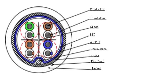
Technical parameter
| Type | CAT6A SF/UTP 23AWG×4P |
| (mm) Specification | |
| Conductor | |
| Conductor material | BC |
| Conductor size | 23AWG×4P |
| Conductor Construction (mm) | 0.57±0.01 |
| Insulation | |
| Insulation material | FOAM+PE |
| Insulation diameter (mm) | 1.35±0.05 |
| Average Thickness (mm) | 0.36 |
| Min Thickness (mm) | 0.3 |
| Color | Blue, White, Orange, White, Green, White, Brown, White |
| Fill | |
| Fill material | PE Cross |
| Pair screen | |
| Shield material | AL Foil |
| Drain wire | |
| Drain wire material | TC |
| Drain wire size(mm) | 1×0.4NOM |
| Drain wire amount | 1 Stick |
| Braid | |
| Braid material | TC |
| Braid coverage | 40% |
| Rip-cord | |
| Rip-cord | Yes |
Detailed technical parameters
| Type | CAT6A SF/UTP 23AWG×4P | ||||||
| (mm)Specification | |||||||
| Jacket | |||||||
| Jacket material | LSZH | ||||||
| Jacket Diameter(mm) | 7.5±0.2 | ||||||
| AverageThickness(mm) | 0.6 | ||||||
| MinThickness(mm) | 0.5 | ||||||
| Color | According to customer's requirement | ||||||
| Electrical&Physical Characteristics: | |||||||
| Conductor DCR 20℃ | ≤72.0 Ω/km | ||||||
| Operational Temperature | -20℃~+90℃ | ||||||
| Rated Voltage | 300V | ||||||
| Characteristic Impedance(Ohm) | 100±15 | ||||||
|
Frequency (MHz) |
Attenuation (dB) |
NEXT (dB) |
PSNEXT (dB) |
ELFEXT (dB) |
PSELFEXT (dB) |
Return loss (dB) |
Delay (ns) |
| 4 | 3.8 | 66.3 | 63.3 | 56 | 53 | 23 | 552 |
| 8 | 5.3 | 61.8 | 58.8 | 49.9 | 46.9 | 24.5 | 547 |
| 10 | 5.9 | 60.3 | 57.3 | 48 | 45 | 25 | 545 |
| 16 | 7.5 | 57.2 | 54.2 | 43.9 | 40.9 | 25 | 543 |
| 20 | 8.4 | 55.8 | 52.8 | 42 | 39 | 25 | 542 |
| 25 | 9.4 | 54.3 | 51.3 | 40 | 37 | 24.3 | 541 |
| 31.25 | 10.5 | 52.9 | 49.9 | 38.1 | 35.1 | 23.6 | 540 |
| 62.5 | 15 | 48.4 | 45.4 | 32.1 | 29.1 | 21.5 | 539 |
| 100 | 19.1 | 45.3 | 42.3 | 28 | 25 | 20.1 | 538 |
| 200 | 27.6 | 40.8 | 37.8 | 22 | 19 | 18 | 537 |
| 250 | 31.1 | 39.3 | 36.3 | 20 | 17 | 17.3 | 536 |
| 300 | 34.3 | 38.1 | 35.1 | 18.5 | 15.5 | 17.3 | 536 |
| 400 | 40.1 | 36.3 | 33.3 | 16 | 13 | 17.3 | 536 |
| 500 | 45.3 | 34.8 | 31.8 | 14 | 11 | 17.3 | 536 |

 sales@jiahengcable.com
 +86-19357267601

 Heziwu, Shuangyuan Village, Linglong Subdistrict, Lin'an District, Hangzhou City, Zhejiang Province, P.R.China
Copyright © Hangzhou Linan Jiaheng Cable Co., Ltd. All Rights Reserved
