

 English
 Ethernet Cable
Home / Products / Ethernet Cable / CAT5e F/UTP LSZH Patch Cable 26AWG Stranded Foil Screened Ethernet Lead

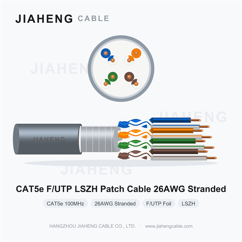
Confirmed Cable Specifications
• Category: CAT5e (Class D), bandwidth 100 MHz
• Shielding: F/UTP — Overall aluminium foil screen (individual pairs unshielded)
• Jacket: LSZH (Low Smoke Zero Halogen)
• Conductor size: 26AWG (approx. 0.40 mm diameter)
• Conductor type: Stranded conductor (26AWG is typically stranded, suitable for patch cords)
• Pairs: 4 pairs (8 cores)
1. Product Overview
CAT5e F/UTP LSZH 26AWG×4P combines three features that point to a specific and deliberate use: a stranded 26AWG conductor, an overall aluminium foil screen and an LSZH jacket. This is not a cable for pulling through conduit between a floor distributor and a wall outlet. It is a cable for the last metre — for patch cords, equipment leads and short interconnections where flexibility, interference immunity and fire-safe materials all matter at once.
Read together, the designation tells you exactly what the product is for, and understanding that is what prevents it being misapplied.
2. Stranded 26AWG: Built to Be Bent
A permanent-link cable uses solid conductors because they are dimensionally stable, terminate reliably into insulation-displacement contacts and have the lowest resistance per metre. But solid copper work-hardens. Flex it repeatedly and it eventually cracks.
A patch cord lives the opposite life. It is plugged and unplugged, coiled and uncoiled, routed around desk legs and through cable managers, and flexed every time someone moves a device. Stranded conductors — many fine wires bundled together — tolerate this. Each individual wire is thin enough to flex without accumulating fatigue, so the bundle survives thousands of bending cycles that would break a solid core.
The trade-off is resistance. At 26AWG the conductor is appreciably thinner than the 23AWG or 24AWG used in horizontal cabling, so DC resistance per metre is higher and the maximum practical run length is shorter. This is acceptable precisely because patch cords are short. It is not acceptable in a permanent link, where the added resistance and the difficulty of terminating stranded wire into IDC contacts degrade channel performance.
3. What the Foil Screen Adds Here
F/UTP places an aluminium foil screen around all four pairs, with the individual pairs themselves unscreened. On a short patch cord the question is fair: at one or two metres, is screening worth anything?
It is, in specific situations. Patch cords sit in the most electrically crowded part of any installation — behind desks, inside patch panels, bundled with dozens of other leads and frequently running close to power adapters, chargers, desk lighting transformers and equipment power supplies. These are exactly the sources of the high-frequency noise that can affect a data link. A foil screen intercepts that coupled noise and provides a defined path to earth rather than leaving the pairs exposed.
The screen only works if it is terminated. Foil without a drain wire cannot be connected reliably, and a screen left floating at both ends contributes almost nothing. Confirm whether a drain wire is included, and whether the connectors and patch panel ports used will actually bond the screen to earth.
4. LSZH on a Patch Cord
Patch cords are the most exposed cable in a building: they run across occupied floor space, through corridors and inside rooms where people spend their day. In a fire they burn close to occupants and close to escape routes, and they are numerous. LSZH material reduces smoke density and eliminates corrosive halogen gases, which matters in exactly these locations. In regulated premises — transport hubs, healthcare, education, high-rise buildings — the requirement typically applies to all cabling in the space, patch cords included, not only to the concealed permanent link.
5. Applications
• Patch cords between patch panels and switches in racks and cabinets
• Work area leads from wall outlet to PC, IP phone, printer or thin client
• Equipment interconnection in security, audio-visual and control systems
• Short runs in electrically noisy locations: near VFDs, power supplies, lighting ballasts
• Machine and cabinet internal wiring where repeated flexing is expected
• Any LSZH-mandated environment requiring flexible connecting leads
6. Selection Notes
Do not use this cable for permanent links. Its higher conductor resistance, shorter maximum length and stranded construction make it unsuitable for channel certification, and most structured cabling standards explicitly require solid conductors for the permanent link with stranded conductors reserved for patch cords and equipment leads.
For maximum flexibility, consider ordering pre-terminated cords. Factory termination with moulded boots and tested connectors gives better and more consistent performance than field-assembled plugs, particularly for 26AWG stranded wire, which is difficult to terminate neatly by hand. Specify length, colour and connector type when ordering.
7. Ordering Guidance
Confirm conductor material, stranding construction, whether a drain wire is present, and whether cords are supplied bulk or pre-terminated. If pre-terminated, state the required lengths and whether both ends are RJ45 or one end is bare for custom termination.
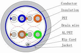
Technical parameter
| Type | CAT5e F/UTP 26AWG×4P |
| (mm) Specification | |
| Conductor | |
| Conductor material | BC |
| Conductor size | 26AWG×4P |
| ConductorConstruction(mm) | 0.40±0.01 |
| Insulation | |
| Insulation material | PE |
| Insulation diameter (mm) | 0.78±0.05 |
| Average Thickness (mm) | 0.18 |
| Min Thickness (mm) | 0.15 |
| Color | Blue, White/Blue, Orange, White/Orange, Green, White/Green, Brown, White/Brown |
| Wrapping tape | |
| Wrapping tape material | PET |
| Drain wire | |
| Drain wire material | TC |
| Drain wire size(mm) | 1/0.404±0.005 |
| Shield | |
| Shield material | AL/PET |
| Rip-cord | |
| Rip-cord | Yes |
Detailed technical parameters
| Type | CAT5e F/UTP 26AWG×4P | ||||||
| (mm) Specification | |||||||
| Jacket | |||||||
| Jacket material | LSZH | ||||||
| Jacket diameter (mm) | 4.8±0.2 | ||||||
| Average Thickness (mm) | 0.6 | ||||||
| Min Thickness (mm) | 0.5 | ||||||
| Color | According to customer’s requirement | ||||||
| Electrical & Physical Characteristics: | |||||||
| Conductor DCR 20℃ | ≤148 Ω/km | ||||||
| Operational Temperature | -20℃~+90℃ | ||||||
| Characteristic Impedance (Ohm) | 100±15 | ||||||
| Channel transmission performance (90M) | |||||||
|
Frequency (MHz) |
Attenuation (dB) |
NEXT (dB) |
PSNEXT (dB) |
ACRF (dB) |
PSACRF (dB) |
Return loss (dB) |
Delay (ns) |
| 1 | 2.2 | 60 | 57 | 57.4 | 54.4 | 17 | 580 |
| 4 | 4.5 | 53.5 | 50.5 | 45.4 | 42.4 | 17 | 562 |
| 8 | 6.3 | 48.6 | 45.6 | 39.3 | 36.3 | 17 | 557 |
| 10 | 7.1 | 47 | 44 | 37.4 | 34.4 | 17 | 555 |
| 16 | 9.1 | 43.6 | 40.6 | 33.3 | 30.3 | 17 | 553 |
| 20 | 10.2 | 42 | 39 | 31.4 | 28.4 | 17 | 552 |
| 25 | 11.4 | 40.3 | 37.3 | 29.4 | 26.4 | 16 | 551 |
| 31.25 | 12.9 | 38.7 | 35.7 | 27.5 | 24.5 | 15.1 | 550 |
| 62.5 | 18.6 | 33.6 | 30.6 | 21.5 | 18.5 | 12.1 | 549 |
| 100 | 24 | 30.1 | 27.1 | 17.4 | 14.4 | 10 | 548 |

 sales@jiahengcable.com
 +86-19357267601

 Heziwu, Shuangyuan Village, Linglong Subdistrict, Lin'an District, Hangzhou City, Zhejiang Province, P.R.China
Copyright © Hangzhou Linan Jiaheng Cable Co., Ltd. All Rights Reserved
