

 English
 Industry News
Home / News / Industry News / How to Choose Industrial Instrumentation Cables for Reliable Signal Transmission

Content
Industrial measurement and control systems depend on reliable transmission of low-level electrical signals between field instruments, monitoring equipment, controllers, and data acquisition systems. Unlike cables designed primarily for power delivery, instrumentation cables are selected according to signal characteristics, electrical interference, environmental exposure, installation conditions, and the requirements of the connected equipment.
An industrial instrumentation cable typically connects transmitters, sensors, control valves, analytical instruments, and other devices used to measure or regulate industrial processes. Depending on the application, its construction may include one or more twisted pairs, individual pair shields, an overall shield, drain wires, protective insulation, and an outer jacket.
Correct cable selection helps maintain signal stability, reduce electromagnetic interference, simplify commissioning, and support dependable long-term operation. The most suitable design is determined by the complete installation environment rather than by conductor size or shielding alone.
Analog, digital, pulse, or communication signals
Pair shielding, overall shielding, or combined protection
Indoor, outdoor, tray, conduit, or industrial equipment routing
An instrumentation cable carries electrical signals used to monitor, measure, or control an industrial process. These signals may represent pressure, temperature, flow, liquid level, equipment status, valve position, or analytical measurements. The cable provides the electrical connection between the field device and the equipment that interprets or acts on the transmitted information.
In a typical process control loop, a field transmitter measures a process variable and converts the measurement into an electrical signal. The signal travels through the cable to a control system, where it is displayed, recorded, compared with a target value, or used to initiate a control response.
Measures a process condition
Transmits the electrical signal
Processes and displays information
Supports monitoring or regulation
Instrumentation circuits do not all operate in the same way. The signal format influences conductor arrangement, electrical performance requirements, and the acceptable installation method.
Low-level signals can be affected by electrical noise, excessive cable resistance, poor termination, and grounding errors. Cable construction must therefore match the characteristics of the connected circuit. A cable suitable for a conventional analog loop may not automatically be suitable for a high-speed data interface or a specialized measurement circuit.
Signal compatibility comes first. Verify the electrical requirements of the instrument and receiving equipment before comparing cable constructions. Shielding and mechanical protection cannot compensate for an incompatible cable design.
Instrumentation cables are commonly differentiated by conductor arrangement, number of pairs, shielding configuration, insulation material, and intended operating environment. Understanding these distinctions helps engineers specify the cable without paying for unnecessary features or overlooking important requirements.
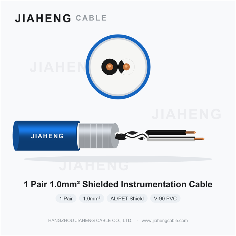
Contains two conductors arranged as one pair. It is commonly considered for an individual measurement loop, a dedicated instrument connection, or a circuit requiring a clearly separated signal path.
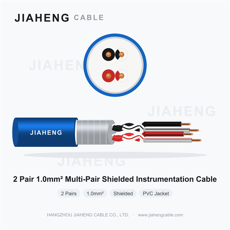
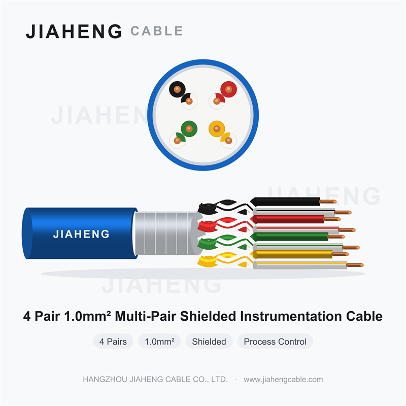
Groups several twisted pairs within one outer sheath. It can consolidate multiple instrument connections between a field junction box and a control room, reducing the need for separate cable runs.
Uses a shared conductive shield around the cable core. This arrangement provides a common shielding layer for the grouped conductors and may be appropriate where the overall cable requires electromagnetic interference protection.
Provides a shield around each pair, helping reduce coupling between adjacent signal circuits. An additional overall shield may be included when the installation also requires common protection against external interference.
Single-pair cables are straightforward to identify and route when a dedicated circuit is required. They can also make troubleshooting easier because each cable corresponds to a clearly defined connection. However, installations containing many individual instruments may require extensive tray space and a large number of cable entries.
Multi-pair construction combines several circuits in a common jacket. Pair identification, conductor numbering, and termination documentation become especially important as the number of circuits increases. Designers should consider spare pairs, segregation between signal types, junction box capacity, and the consequences of a single cable fault affecting several measurements.
Twisting the two conductors of a pair helps reduce the effect of externally induced interference when the circuit and its receiving equipment are designed to benefit from balanced transmission. Consistent twisting also helps control the electrical relationship between the conductors along the cable length.
The actual performance depends on conductor geometry, twist construction, cable capacitance, shielding, installation conditions, and termination quality. A twisted pair should not be treated as a universal solution for every electrical noise problem.
Shielding is a major selection factor for cables installed near motors, variable frequency drives, switching equipment, power distribution systems, and other potential sources of electromagnetic interference. A conductive shield helps control the coupling of unwanted electrical noise into the signal circuit, provided that the shield, grounding arrangement, and installation are properly engineered.
Common shielding materials include aluminum-polyester foil, copper tape, braided copper, and combinations of foil and braid. These constructions differ in coverage, flexibility, mechanical characteristics, and electrical performance. No single material is automatically best for every industrial installation.
Relative assessment for preliminary selection, not measured attenuation or a product test result
An overall shielded twisted pair cable places a conductive shield around one or more twisted pairs. It is commonly considered for installations where several conductors share a common protective shield and the circuit design does not require a separate shield around every pair.
Foil shields can provide extensive surface coverage and are often used with a drain wire to simplify electrical connection to the shield. Braided shields offer a woven conductive structure that can provide mechanical flexibility and a different balance of electrical characteristics. Combined foil and braid constructions can be specified where the application requires complementary shielding properties.
In multi-pair cables, individual pair shields help reduce unwanted coupling between neighboring circuits. A common outer shield can provide an additional layer against external interference. This construction is useful to evaluate when sensitive analog measurements, different signal sources, or demanding control requirements are present within the same cable.
However, more shielding is not always the most economical or technically necessary solution. The final choice should consider the source of interference, signal amplitude, cable length, circuit impedance, frequency range, grounding strategy, and manufacturer test data.
| Construction | Primary Consideration | Potential Limitation |
|---|---|---|
| Unshielded twisted pair | Simple construction and cost control | May be unsuitable for electrically noisy routes |
| Overall foil shield | Broad conductive coverage | Requires appropriate handling and termination |
| Braided shield | Woven conductive coverage and flexibility | Coverage and high-frequency performance vary by braid design |
| Individually shielded pairs | Reduced coupling between pairs | More complex cable construction and termination |
| Individual and overall shields | Combined pair isolation and external shielding | Higher material cost and greater termination complexity |
Shielding selection should begin with the actual interference problem rather than a general preference for a particular shield material. Electrical noise may originate from power switching, motor operation, adjacent cables, grounding differences, or electromagnetic fields produced by industrial equipment.
Determine whether the signal route passes near motor feeders, switching devices, high-current conductors, or radio-frequency equipment. Record the separation distance and any available site interference measurements.
Check the instrument output, receiving input, expected signal range, permissible noise, and measurement accuracy requirements. Low-level or high-impedance signals may need particular attention.
Decide whether shared shielding is adequate or whether separate pair shields are justified by circuit isolation and interference considerations.
Specify the shield termination method, drain wire treatment, bonding arrangement, and applicable equipment grounding requirements before installation begins.
Shield grounding is frequently discussed in terms of connection at one end or at both ends. Neither method should be applied as a universal rule. The correct arrangement depends on the signal frequency, system grounding architecture, equipment design, potential differences between locations, and the recommendations for the connected devices.
Single-ended shield grounding is sometimes used in low-frequency analog circuits to reduce circulating shield currents caused by ground potential differences. At higher frequencies, grounding at both ends or additional bonding arrangements may be necessary to provide a suitable high-frequency path. The effectiveness of a shield depends on the complete installation, not simply on the number of grounded ends.
In some industrial systems, a properly engineered equipotential bonding network and defined shield termination practices are more important than choosing a grounding method in isolation. Follow the instrument documentation and applicable electrical installation requirements. Where the consequences of interference are significant, involve the control system and electrical engineering teams before standardizing the wiring practice.
Shielding is only one part of cable specification. Conductor cross-sectional area, insulation properties, jacket material, operating temperature, mechanical requirements, and installation conditions all influence suitability.
Instrumentation cables may use conductor sizes such as 0.5, 0.75, 1.0, or 1.5 square millimeters, depending on the application and manufacturer design. These values are examples of commonly encountered sizes rather than a universal range. The required conductor size should be established from circuit resistance, cable length, current, signal requirements, terminal compatibility, and applicable project specifications.
For a 4 to 20 mA loop, excessive conductor resistance can reduce the voltage available to the transmitter or receiving equipment. Long cable routes and circuits containing additional devices require a complete loop budget. Designers should also consider conductor resistance at the expected operating temperature, not only its nominal value at room temperature.
Insulation separates conductors and influences electrical performance, temperature capability, flexibility, and compatibility with the surrounding environment. Common industrial cable constructions may use polyethylene, cross-linked polyethylene, polyvinyl chloride, or other materials selected for the intended service.
The jacket protects the cable core from mechanical contact, abrasion, moisture exposure, and other environmental conditions. PVC and low-smoke zero-halogen compounds are among the materials that may be specified, but they serve different design and compliance considerations. Flame performance, smoke emission, gas acidity, chemical resistance, ultraviolet exposure, and temperature ratings must be checked against the actual product documentation.
Outdoor installations may require resistance to sunlight, water ingress, and temperature cycling. Industrial washdown areas may introduce moisture and cleaning chemicals. Cable routes near oils, solvents, or process fluids require material compatibility verification rather than reliance on generic descriptions such as oil resistant or chemical resistant.
Illustrative relative priority scores for specification planning
A suitable material specification should refer to verified product ratings and test reports. General material names alone do not establish a cable's allowable temperature, chemical resistance, flame classification, or suitability for a hazardous location.
Instrumentation cables are used across industries where process measurements and equipment status must be communicated to control or monitoring systems. The required construction depends on the process, the signal interface, environmental exposure, and the consequences of a communication failure.
Field transmitters, pressure monitoring devices, tank level instruments, valve position feedback, and process analyzers may require signal connections across extensive industrial sites. Cable selection must account for outdoor exposure, hazardous-area requirements, mechanical protection, and the project's electrical installation standards.
Process measurementTemperature, pressure, flow, and level measurements support process monitoring and control. Chemical compatibility, cable routing, separation from power circuits, and the need to preserve individual measurement signals are key specification considerations.
Process controlInstrumentation can monitor flow rates, tank levels, pressure, water quality, and pump operating status. Moisture resistance, outdoor suitability, and compatibility with the installation environment are often important when choosing cable materials and protective arrangements.
Environmental monitoringMeasurement circuits support equipment monitoring, plant automation, auxiliary system control, and condition assessment. Designers should evaluate electromagnetic interference from switching equipment, segregation requirements, temperature exposure, and the applicable fire-performance specifications.
Equipment monitoringIndustrial sensors and control devices exchange measurement and status information across production equipment. Cable flexibility, bending requirements, resistance to abrasion, and the movement profile of the installation can be important, particularly near machinery and automated handling systems.
Factory automationA cable selected for a protected control room installation may not be appropriate for an exposed outdoor route. Similarly, a construction suitable for static cable trays may not meet the repeated bending or torsional movement requirements of a moving machine.
Engineers should distinguish between ordinary instrumentation circuits and specialized communication systems. Protocol-specific networks, high-speed digital links, intrinsically safe circuits, and fire alarm systems may impose additional requirements that cannot be confirmed solely from the term instrumentation cable. Verify the cable's declared intended use, electrical characteristics, and compliance documentation before assigning it to these applications.
Reliable signal transmission requires more than an appropriate nominal voltage rating. Cable resistance, capacitance, conductor balance, shielding continuity, insulation condition, cable length, and installation practices can all affect the performance of a measurement circuit.
Every conductor has electrical resistance. As cable length increases, conductor resistance becomes more significant in current loops and other circuits where the available voltage is limited. An engineer should confirm that the transmitter, cable, receiving input, and any additional devices can operate within their specified electrical limits under the most demanding expected conditions.
For voltage signals, the interaction between source impedance, cable capacitance, and receiving input impedance may influence signal response and accuracy. For current loops, cable resistance affects the voltage required to maintain the intended current. The correct evaluation depends on the circuit architecture and instrument specifications.
Cable capacitance can influence signal behavior, particularly for high-impedance circuits, fast transitions, long cable runs, and communication signals. Capacitance between conductors and between conductors and shields should be checked when required by the instrument or communication interface specifications.
Low-frequency analog loops and faster digital communication circuits have different performance requirements. A cable that functions adequately in one application should not be assumed to meet the bandwidth, impedance, attenuation, or timing requirements of another.
Electromagnetic interference can appear as fluctuating readings, unexpected changes in measured values, intermittent communication faults, or unstable control behavior. Potential sources include power switching, motors, contactors, variable frequency drives, and adjacent electrical conductors.
Effective mitigation begins with appropriate cable routing and separation, followed by suitable twisted-pair construction, shielding, bonding, and termination. Corrective action should address the actual coupling mechanism. Adding a shield without correcting a poor grounding connection or unsuitable routing may provide limited improvement.
Conceptual index over an example commissioning period
When a signal quality problem occurs, record the original symptoms before changing the wiring. Compare the reading at the field instrument with the value received by the control system. Where permitted, inspect shield continuity, termination quality, cable routing, grounding, and the condition of the connected equipment.
Even a correctly specified cable can perform poorly if it is damaged during installation or connected incorrectly. Installation requirements should therefore be included in project documentation, cable schedules, inspection procedures, and commissioning records.
Review tray capacity, cable segregation, power circuit proximity, environmental exposure, and access for maintenance. Apply the separation and crossing practices required by the project standards.
Follow the manufacturer's minimum bend radius for the actual cable construction and installation condition. Avoid tight bends, kinks, excessive pulling tension, and damage to shielding or insulation.
Prevent moisture, dirt, and conductive debris from entering exposed cable cores. Use compatible glands, seals, and enclosure entries where required by the installation design.
Follow the documented shield and drain wire arrangement. Maintain the intended shield continuity and avoid accidental contact between exposed shield components and signal terminals.
Signal cables should be routed according to the required separation from power conductors and other interference sources. The appropriate distance depends on the installation standard, cable construction, power circuit characteristics, shielding, and the type of instrumentation signal.
Where signal and power routes must cross, the project design may require a crossing arrangement that minimizes the length of parallel exposure. Metallic trays, conduits, partitions, and bonding may form part of the mitigation strategy when correctly designed and installed. Do not assume that a metal enclosure alone guarantees immunity to interference.
Pair numbers, conductor colors, terminal numbers, and cable identifiers should match the approved drawings and cable schedule. Consistent identification is particularly important in multi-pair installations, where an incorrect pair assignment can cause misleading measurements or disrupt more than one circuit.
Shield and drain wire terminations should be neat, secure, and appropriate for the selected shield construction. Excessive removal of shielding can create an unnecessarily exposed section of conductors. The termination method should maintain electrical integrity while satisfying enclosure, insulation, and serviceability requirements.
Instrumentation faults can originate in the field instrument, the cable, the termination, the control input, or the surrounding electrical environment. A structured troubleshooting method helps distinguish cable-related problems from equipment failures and avoids unnecessary replacement.
| Observed Symptom | Possible Cause | Recommended Check |
|---|---|---|
| Unstable readings | Electromagnetic interference, loose termination, grounding issue | Review routing, shield continuity, grounding, and terminal tightness |
| No signal | Open conductor, incorrect pair assignment, power supply issue | Verify loop continuity, instrument supply, and terminal connections |
| Incorrect measurement | Polarity error, resistance-related voltage loss, wrong configuration | Compare field output, loop conditions, and receiving input settings |
| Intermittent faults | Damaged conductor, moisture ingress, loose connection | Inspect cable entries, junction boxes, exposed sections, and terminations |
| Communication errors | Impedance mismatch, excessive capacitance, unsuitable cable type | Check interface specifications, cable parameters, topology, and termination |
Begin by confirming whether the problem affects one measurement or several. A single affected circuit may indicate a local instrument, conductor, or termination problem. Multiple circuits failing at the same time can suggest a shared cable, common grounding issue, power disturbance, or control system problem.
Next, compare the signal at the source and at the receiving end using approved measurement procedures. If the field device produces a stable signal but the receiving equipment shows an unstable value, investigate the intervening cable, terminations, grounding, and input configuration. If the source itself is unstable, check the instrument, process condition, and its power supply before concluding that the cable is defective.
Insulation resistance tests and continuity tests can help identify certain cable faults, but the test method and voltage must be compatible with the cable and all connected equipment. Disconnect sensitive electronic devices where required by the approved procedure. Never apply an insulation test voltage to connected instruments unless the equipment manufacturer and test procedure explicitly permit it.
After identifying the fault, document the cause and the corrective action. If several similar faults occur in the same route, review the installation design and cable specification instead of treating each incident as an unrelated failure.
Industrial instrumentation cable specifications should describe the complete cable construction and its required performance. A short description such as shielded two-pair cable is rarely sufficient for purchasing, quality inspection, or installation approval.
The applicable standards depend on the intended market, industrial sector, electrical classification, and project requirements. Some projects specify recognized instrumentation cable construction standards, while others use a combination of national standards, IEC publications, customer requirements, and site-specific engineering documents.
A statement that a cable is manufactured to a particular standard should be supported by documentation showing the applicable construction and test requirements. A general compliance statement does not necessarily establish suitability for every environmental condition or communication protocol.
Likewise, a test result applies to the tested sample, construction, method, and conditions. Procurement teams should verify that the submitted documentation corresponds to the offered cable design rather than to a superficially similar product. When project approval requires third-party certification or specific fire tests, confirm the exact scope of the certification before purchase.
Comparing cable options requires a consistent set of criteria. Price alone cannot show whether a construction is appropriate for a given circuit, while a longer list of features does not automatically indicate better performance.
The radar chart below demonstrates a hypothetical comparison between three construction approaches. Its scores are illustrative and are intended to show how engineers can organize a specification review. They are not product test results and should not be used as a substitute for manufacturer data.
Illustrative scores from 1 to 5, with higher scores representing a stronger fit for the stated criterion
For procurement and engineering reviews, replace illustrative scores with verified information from product datasheets, test reports, installation drawings, and supplier quotations. The comparison should also distinguish mandatory requirements from preferences.
| Evaluation Criterion | Evidence to Review | Decision Question |
|---|---|---|
| Electrical compatibility | Resistance, capacitance, rated voltage, applicable impedance data | Does the cable meet the circuit requirements? |
| Shielding | Shield material, coverage, construction, termination requirements | Is the shielding suitable for the interference environment? |
| Environmental suitability | Temperature, UV, moisture, chemical, and fire-performance ratings | Does the product meet site conditions? |
| Installation compatibility | Bend radius, pulling limits, cable diameter, tray arrangement | Can it be installed without damage? |
| Quality assurance | Inspection reports, test certificates, traceability, manufacturing records | Can the supplied product be verified? |
| Commercial suitability | Lead time, minimum order, available lengths, packaging, lifecycle cost | Can supply requirements be met reliably? |
A documented selection workflow helps engineering and purchasing teams avoid incomplete specifications. It also provides a consistent basis for comparing quotations from different manufacturers.
Record the instrument output, receiving interface, signal type, expected circuit length, conductor resistance limits, capacitance limits, and any communication protocol requirements. Determine whether the cable carries one circuit or multiple independent signals.
Identify indoor and outdoor sections, moisture exposure, chemicals, temperature extremes, mechanical stress, cable movement, electromagnetic noise, and any classified hazardous areas. Define the required mechanical protection and routing method.
Select conductor size, pair count, twisting arrangement, shield configuration, insulation, jacket, and any additional protection. Consider spare pairs and future maintenance needs where multiple circuits share a cable.
Compare the proposed cable datasheet with every mandatory specification. Confirm ratings and required test evidence rather than relying only on a general product description. Resolve missing information before issuing a purchase order.
Confirm manufacturing lead time, required cable lengths, packaging, identification, documentation, inspection requirements, and order quantities. For customized constructions, ensure the approved drawing and datasheet describe the same product configuration.
Verify the delivered cable against the approved specification. Complete installation inspections and appropriate electrical tests, record the results, and retain the final cable schedule for future maintenance and fault diagnosis.
When sourcing industrial instrumentation cable for a plant project, an engineering contractor, or an equipment manufacturing program, procurement teams should provide enough technical information for the supplier to identify a compatible construction. Clear specifications reduce ambiguity and make quotations easier to compare.
An experienced instrumentation cable manufacturer should be able to explain available conductor arrangements, shielding options, insulation and jacket materials, applicable electrical characteristics, production capabilities, and relevant quality documentation. The supplier should also identify any requirements that cannot be met by the proposed standard construction.
Where the project requires a customized cable, the technical review should establish the exact construction before mass production. Changes to conductor size, pair arrangement, shielding material, jacket compound, or cable diameter may affect performance, installation compatibility, and compliance documentation.
Purchasers should also confirm that the offered product can be manufactured consistently and supplied with appropriate identification and quality records. Sample evaluation may be useful for specialized applications, but the acceptance criteria should be agreed upon before the sample is tested.
Does the proposed cable meet the electrical requirements of the actual instrument circuit?
Is the shielding construction appropriate for the identified interference environment?
Are material ratings, compliance documents, and test reports available for review?
Can the cable be supplied in the required lengths, quantities, packaging, and schedule?
The objective is to establish a technically suitable and verifiable specification. A well-defined inquiry supports accurate quotations, reduces the risk of substitutions, and provides a clearer basis for inspection and acceptance.
An industrial instrumentation cable transmits electrical signals between field instruments and monitoring or control equipment. Typical applications include pressure, temperature, flow, and level measurement, equipment status monitoring, and process control.
Instrumentation cable is generally designed around signal transmission, electrical noise control, and circuit identification. Power cable is primarily designed to deliver electrical power. Their conductor construction, insulation, ratings, and installation requirements differ according to the intended application.
It is a cable construction that uses twisted conductor pairs inside a shared conductive shield. The shield helps control electromagnetic interference, while twisting supports the electrical balance of the pair. Suitability depends on the circuit, interference environment, and termination arrangement.
Individual pair shielding may be appropriate when several sensitive signals share one cable and coupling between circuits needs to be controlled. The decision should consider signal sensitivity, interference sources, system grounding, cable construction, and project requirements.
The correct method depends on signal frequency, grounding architecture, equipment requirements, and possible ground potential differences. Single-ended grounding is sometimes used for low-frequency analog circuits, while both-ended bonding may be needed for certain higher-frequency applications. Follow the approved system design rather than applying one rule to every installation.
The required conductor size depends on cable length, loop resistance, available supply voltage, instrument voltage requirements, receiving equipment, temperature, and applicable specifications. Common nominal sizes include 0.75 and 1.0 square millimeters in some installations, but these are examples rather than universal recommendations. Confirm the complete loop requirements before selection.
Yes, when the selected construction is rated for the actual outdoor conditions. The specification should address ultraviolet exposure, moisture, temperature variation, mechanical protection, and any chemical or fire-performance requirements. An indoor cable should not be assumed suitable for outdoor use without supporting documentation.
Potential causes include electromagnetic coupling from power equipment, poor shielding termination, grounding problems, damaged conductors, loose terminals, and unsuitable cable routing. Compare the field signal with the received signal and inspect the entire circuit before deciding whether the cable requires replacement.
Provide the signal application, conductor size, number of pairs, shielding configuration, insulation and jacket materials, temperature and environmental requirements, applicable standards, cable length, order quantity, and documentation requirements. Include a technical drawing or approved specification when a customized construction is needed.
Review the product datasheet, applicable standard requirements, conductor and insulation test results, shielding construction, material ratings, and required compliance documents. Verify that the documents match the actual offered cable and perform the specified incoming inspection and acceptance tests.

 sales@jiahengcable.com
 +86-19357267601

 Heziwu, Shuangyuan Village, Linglong Subdistrict, Lin'an District, Hangzhou City, Zhejiang Province, P.R.China
Copyright © Hangzhou Linan Jiaheng Cable Co., Ltd. All Rights Reserved Custom Industrial Wire and Cables Suppliers
