

 English
 Industry News
Home / News / Industry News / Essential Standards and Specifications for Fire Alarm Wiring Cables in Commercial Buildings

Content
Fire alarm wiring is a critical part of a building's life safety infrastructure. The selected cable must support reliable communication between initiating devices, control equipment, notification appliances, and other connected systems under the environmental and operating conditions specified by the system design.
For commercial buildings, cable selection involves more than conductor size or nominal voltage. Engineers and contractors must evaluate fire alarm circuit classification, cable listing, installation location, flame propagation, smoke performance, electromagnetic interference, circuit survivability, and the requirements adopted by the local authority.
This guide explains how to evaluate fire alarm wiring cable against applicable standards and project requirements, with practical comparisons and installation checks for commercial construction.
These references identify important areas of review, not a complete compliance checklist. The adopted code edition, project specifications, equipment instructions, and local approval requirements determine the final selection.
Commercial fire alarm installations may be subject to several interconnected standards. Each addresses a different part of the system, so compliance cannot be established by checking a cable marking in isolation.
The National Electrical Code provides wiring and installation requirements. Article 760 addresses fire alarm systems, including power-limited and non-power-limited circuits, cable types, separation, protection, and permitted installation methods.
The National Fire Alarm and Signaling Code addresses system design, pathway performance, monitoring, inspection, testing, and maintenance. It is especially important when evaluating the continued operation of designated life safety functions during a fire.
This standard covers cables for power-limited fire alarm circuits, including FPL, FPLR, and FPLP types. It addresses cable construction and relevant fire and smoke performance tests for the applicable classifications.
This standard concerns fire testing for circuit integrity of fire-resistive power, instrumentation, control, and data cables. It is relevant when a project requires a fire-resistive cable system to maintain electrical circuit integrity under specified test conditions.
These documents are complementary rather than interchangeable. A cable may satisfy a product standard but still be unsuitable for a particular building location or circuit function. Similarly, a cable with excellent fire performance is not automatically approved for every fire alarm application.
Always confirm which editions have been adopted by the relevant jurisdiction. A published standard's latest edition does not automatically become the legally applicable edition everywhere. Amendments, local building regulations, and the authority having jurisdiction can affect the requirements.
FPL cable classifications help identify the intended installation environment. They are not simply three levels of general cable quality. Each designation corresponds to a particular use and associated fire performance evaluation.
| Classification | Primary application | Important consideration |
|---|---|---|
| FPL | General fire alarm circuit applications where the classification is permitted | Not automatically suitable for plenum or riser installations requiring a higher classification |
| FPLR | Vertical runs in shafts and qualifying floor-to-floor installations | Verify applicable shaft installation requirements and the exact cable listing |
| FPLP | Plenums and other environmental air-handling spaces where the applicable rules permit this cable type | Confirm the required plenum fire and smoke test classification |
Relative emphasis of the main installation considerations, shown as a qualitative comparison rather than a measured rating.
Under the UL 1424 framework, FPLP cable is evaluated for flame and smoke characteristics associated with environmental air spaces, while FPLR cable is evaluated for vertical flame propagation in shafts. FPL cable is intended for general applications outside the more demanding plenum and riser classifications.
Do not assume that a higher installation classification automatically authorizes every lower-classification application. The permitted substitutions and installation methods must be checked against the adopted electrical code and cable listing.
One of the most important distinctions in fire alarm cable specification is the difference between limiting fire propagation and maintaining an electrical circuit during a fire.
A flame-retardant cable is designed and tested to meet specified fire propagation criteria. Depending on its classification, it may also be evaluated for smoke performance. These characteristics help address how fire may spread along cable routes and how cable combustion products affect the surrounding environment.
A fire-resistive or circuit integrity cable has a different objective: the circuit must continue performing under defined fire test conditions. Whether that performance is required depends on the function of the circuit and the pathway survivability provisions applicable to the project.
For example, an ordinary notification circuit in a permitted installation may require a listed fire alarm cable but not necessarily a two-hour circuit integrity system. A designated emergency control or notification pathway may have additional survivability requirements. The answer depends on the system architecture and applicable provisions, not simply on whether the cable jacket says fire resistant.
Pathway survivability concerns whether designated fire alarm pathways remain capable of performing their intended functions during a fire. This can become particularly important in buildings with phased evacuation, emergency voice communication, smoke control, or other coordinated life safety functions.
NFPA 72 addresses pathway survivability, while NFPA 70 governs applicable wiring methods. Depending on the adopted edition and design, acceptable approaches may include a specified fire-resistive cable, a listed protective cable system, a rated enclosure, a protected area, or an approved alternative.
Determine which alarm, notification, communication, or emergency control functions must remain operational during a fire.
Review the applicable code edition, building protection, evacuation strategy, and approved system design.
Evaluate cable performance, the complete protective system, enclosure construction, and required supporting components.
Check supports, joints, penetrations, terminations, routing, and other details against the approved system documentation.
A fire-resistive cable cannot be evaluated independently from its installation method when the approved performance depends on a complete system. Mounting hardware, supports, connectors, penetrations, and protective enclosures may all affect the assembly's ability to meet its intended performance.
Project teams should record the required survivability criteria in the design documents before procurement. Doing so reduces the risk of substituting a cable that meets a general flame test but does not satisfy the specified pathway performance.
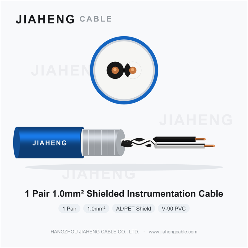
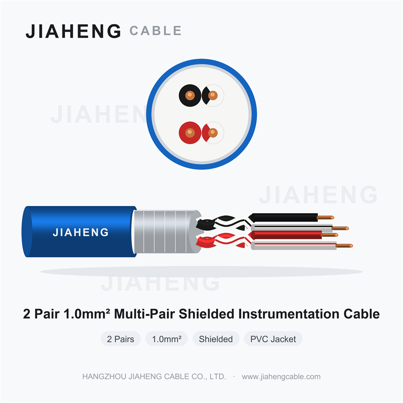
Shielding is used to help control electromagnetic interference in circuits that are sensitive to electrical noise. A shielded fire alarm wire may be considered for analog signaling, addressable communication, or other circuits when the system manufacturer's instructions and engineering design call for it.
Potential interference sources in commercial buildings include variable-frequency drives, motors, transformers, elevator equipment, switching power supplies, and parallel power conductors. The actual risk depends on the source, cable routing, grounding arrangement, signal characteristics, and installation environment.
Qualitative engineering assessment. These categories are not measured scores or guaranteed performance ratings.
Greater separation from a noise source may reduce coupling, but distance alone cannot guarantee reliable signaling. Cable construction, grounding, routing geometry, and equipment compatibility also matter. Follow the installation instructions for the specific fire alarm control equipment and connected devices.
Shielding does not replace the requirements for correct conductor sizing, circuit supervision, separation, fire performance, or pathway survivability. A shielded cable may still be unsuitable if its listing or construction does not match the project specification.
LSZH means low smoke zero halogen. LSZH fire alarm cable is designed to limit smoke generation and the release of halogen-containing gases under specified test conditions. These properties can be important in enclosed or densely occupied spaces where smoke visibility, evacuation, and post-fire equipment damage are concerns.
However, LSZH is a material and performance description, not a universal approval category for fire alarm circuits. A cable marketed as LSZH must still meet the listing, flame performance, circuit rating, and installation requirements that apply to its intended use.
| Selection factor | What to verify |
|---|---|
| Smoke performance | Test method, measured limits, and applicability to the project |
| Halogen content | Declared material properties and supporting test documentation |
| Flame performance | Required flame propagation classification or listing |
| Electrical suitability | Conductor size, voltage rating, insulation, and circuit compatibility |
| Installation approval | Acceptance under the adopted code and local requirements |
Low-smoke and halogen-free properties should be evaluated using the actual declared test standards. Different test methods assess different characteristics, so a general LSZH claim does not establish a specific flame, smoke, toxicity, or circuit integrity rating.
In international projects, specifications may reference different regional cable classifications and test standards. Engineers should confirm that the selected product satisfies the precise requirements stated in the project documents instead of assuming that terminology from one jurisdiction transfers directly to another.
Conductor selection affects electrical performance, installation practicality, and the ability of connected devices to operate within their specified limits. A cable should not be selected solely because its conductor size is commonly used in another building or another fire alarm system.
The engineering review should consider the circuit type, total route length, conductor resistance, expected current, device operating limits, ambient temperature, installation method, and any restrictions imposed by the control equipment manufacturer. For notification appliance circuits, the load and end-of-line voltage are particularly important considerations.
Relative design emphasis varies with the circuit and project; the following illustration is qualitative.
For procurement, request the manufacturer's conductor resistance data and technical documentation rather than relying on an assumed performance value. The final design should be verified against the system's electrical requirements and approved documentation.
The cable's operating environment can be as important as its fire classification. Commercial buildings may contain humid service spaces, exposed rooftop routes, equipment rooms, vibration-prone areas, and locations where cables are subject to abrasion or mechanical damage.
Check conductor material, size, stranding, resistance, and terminal compatibility. Confirm that the construction matches the circuit design and installation instructions.
Verify electrical ratings, temperature limits, and suitability for the expected environmental conditions. Confirm compatibility with the required cable classification.
Review shielding coverage, drain conductor construction, termination instructions, and whether the complete cable assembly is listed for the intended use.
Evaluate flame performance, smoke requirements, abrasion resistance, moisture exposure, sunlight exposure, and any project-specific chemical or mechanical conditions.
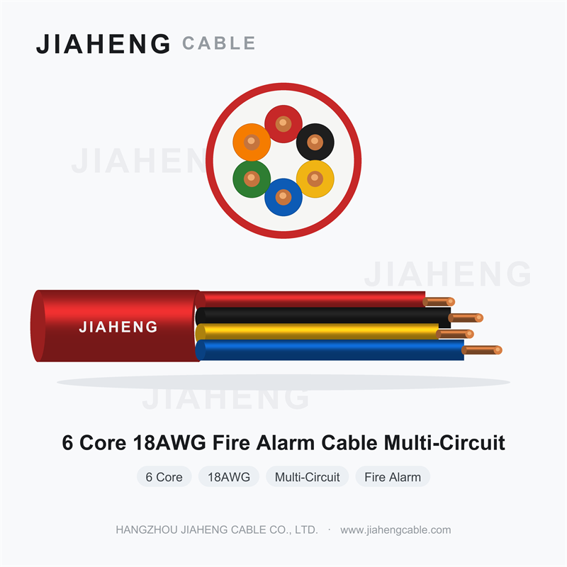
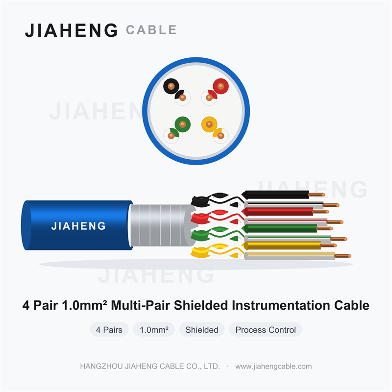
Example of a multi-conductor fire alarm cable construction. Confirm the actual conductor count, gauge, shielding, jacket, listing, and application from the product documentation.
A multi-conductor configuration may simplify certain wiring arrangements, but conductor count alone does not establish compatibility. Spare conductors, if provided, must be handled in accordance with the project design and applicable installation instructions.
Likewise, a temperature rating printed in technical documentation should not be confused with a fire-resistance duration. Normal operating temperature, short-term temperature tolerance, flame test performance, and circuit integrity are separate characteristics.
Good cable selection can be undermined by poor installation. Cable routing, support, bend radius, pulling tension, penetration sealing, and separation from other services all influence the quality and reliability of the completed system.
Firestopping is particularly important when cable routes penetrate fire-resistance-rated walls or floors. The penetration must be protected using a method approved for the specific assembly and conditions. An acceptable cable jacket does not eliminate the need to maintain the fire-resistance function of the building barrier.
Procurement teams need enough technical detail to distinguish compliant cable from products that merely have similar names. A specification that states only fire alarm cable and a conductor gauge can leave important performance requirements unresolved.
A complete procurement schedule should identify the intended circuit, cable classification, conductor construction, environmental requirements, and any special performance criteria. Where a fire-resistive assembly is required, the specification should address the complete approved system rather than only the cable itself.
| Specification field | Required information | Verification evidence |
|---|---|---|
| Application | Detection, signaling, notification, or emergency control | Approved drawings and circuit schedule |
| Code classification | Required cable type and installation location | Product markings and listing documentation |
| Electrical design | Conductor size, count, resistance, and circuit compatibility | Technical data sheet and design calculations |
| Fire performance | Required flame, smoke, or circuit integrity performance | Applicable test reports and approvals |
| Environmental conditions | Temperature, moisture, sunlight, and mechanical exposure | Manufacturer's ratings and installation instructions |
| Quality traceability | Product identification and production documentation | Labels, batch records, and delivery inspection records |
When evaluating a fire alarm cable manufacturer, request current technical data sheets, applicable listing details, test documentation, and instructions for installation and storage. If the project requires third-party certification, verify the exact cable designation and construction instead of relying on a general company statement.
Substitutions should be reviewed by the responsible designer and approved where required. Similar conductor sizes, jacket colors, or marketing descriptions do not establish technical equivalence. Any change affecting the cable classification, electrical performance, survivability, or installation method should be evaluated before procurement and installation.
These terms describe different performance objectives. State whether the design requires flame propagation control, smoke performance, or continued electrical circuit operation during fire exposure.
A cable suitable for general installation may not be permitted in an environmental air plenum or a vertical shaft. Confirm the exact classification and applicable installation rules.
Low-smoke and halogen-free properties do not independently prove circuit integrity, required flame performance, or approval for a particular installation.
Shielding should be coordinated with equipment instructions, circuit design, grounding practices, and routing. An incorrect shield connection may undermine the intended noise-control benefit.
Where survivability is required, the approved cable, supports, connectors, enclosures, and installation method must satisfy the applicable system requirements.
These errors can lead to rejected submittals, installation rework, schedule delays, or deficiencies identified during inspection. A coordinated review involving the fire alarm designer, electrical contractor, procurement team, and approving authority helps identify mismatches before installation begins.
The following radar illustration summarizes five design dimensions that engineers commonly consider. It is a conceptual comparison of selection priorities, not a certification result or a measured ranking of particular products.
The chart should not be used to conclude that one cable category is universally superior. General listed cable may be fully appropriate for a circuit that does not require enhanced survivability. Conversely, a project that requires continued operation during specified fire exposure needs a cable or pathway system approved for that purpose.
Selection is therefore a requirements-matching exercise. First establish the required performance, then evaluate the available constructions and supporting documentation. Avoid selecting a cable based on a visual comparison, a generic product label, or a single performance attribute.
In the United States, NFPA 70 addresses electrical installation requirements, including Article 760, while NFPA 72 addresses fire alarm and signaling system design, performance, inspection, and testing. UL 1424 is relevant to listed power-limited fire alarm cables, and UL 2196 is relevant when fire-resistive circuit integrity is required. The adopted editions and local regulations must be confirmed for each project.
FPL is intended for permitted general fire alarm cable applications, FPLR is intended for qualifying vertical shaft installations, and FPLP is intended for qualifying plenum and environmental air-handling spaces. Each designation has associated performance requirements. The actual installation must comply with the applicable code and cable listing.
Not every fire alarm circuit requires a fire-resistive cable system. The required performance depends on circuit function, pathway survivability provisions, building design, and the adopted code. A flame-retardant cable may be sufficient for some applications, while designated life safety pathways may require circuit integrity or another approved survivability method.
Shielded cable may be appropriate when the system design or equipment manufacturer requires protection against electromagnetic interference. It should be selected with the correct shield construction, routing, grounding, and termination method. Shielding does not replace the required cable listing or fire performance classification.
No. LSZH describes low-smoke and halogen-related material characteristics. The cable must still meet the required electrical, flame, installation, and listing criteria. Any required smoke or halogen performance should be verified using the applicable test documentation.
No. FPLR identifies a riser cable classification, not a two-hour circuit integrity rating. If a project requires continued circuit operation during fire exposure, the specified cable or complete pathway system must meet the applicable fire-resistive requirements.
Consider circuit load, conductor resistance, route length, device operating limits, ambient conditions, conductor material, and equipment instructions. Verify the design using the actual cable data and the requirements of the connected fire alarm equipment rather than selecting a gauge based only on common practice.
Request the current technical data sheet, cable markings and listing information, applicable test reports, conductor resistance data, installation instructions, and relevant quality documentation. For fire-resistive applications, verify the approved assembly and its installation requirements, not just the cable description.
Do not assume that sharing a raceway is permitted. The applicable electrical code, circuit classifications, wiring methods, equipment requirements, and project specifications govern separation and routing. Confirm the specific installation arrangement with the responsible electrical designer and authority having jurisdiction.
Verify the cable classification, product documentation, conductor sizing, route suitability, pathway protection, firestopping, supports, terminations, shield connections, and required testing records. Confirm that the installed arrangement matches the approved drawings and resolves any inspection deficiencies before the system is accepted.
Choosing fire alarm wiring cable for a commercial building requires a coordinated review of electrical code requirements, cable listings, fire and smoke performance, circuit integrity, signal reliability, and installation conditions. FPL, FPLR, FPLP, shielded constructions, and LSZH materials each address specific considerations, but none should be treated as a substitute for a complete compliance review.
The most reliable specification starts with the intended life safety function and the approved system design. It then defines the cable classification, conductor requirements, environmental suitability, and any required pathway survivability performance. Supporting documentation and correct installation complete the process.
By verifying these requirements before procurement and installation, project teams can reduce avoidable substitutions, improve inspection readiness, and support the long-term reliability of commercial fire alarm systems.

 sales@jiahengcable.com
 +86-19357267601

 Heziwu, Shuangyuan Village, Linglong Subdistrict, Lin'an District, Hangzhou City, Zhejiang Province, P.R.China
Copyright © Hangzhou Linan Jiaheng Cable Co., Ltd. All Rights Reserved Custom Industrial Wire and Cables Suppliers
